|
ROSINA: The Mass spectrometer for the Rosetta Mission
|
 |

|
ROSINA: The Mass spectrometer for the Rosetta Mission
|
 |
 ROSINA (The ROsetta Spectrometer for Ion and Neutral Analysis) is the main Mass Spectrometer on the orbiter of ESA’s
 ![]() Rosetta mission to 67P/Churyumov-Gerasimenko.
Rosetta mission to 67P/Churyumov-Gerasimenko.
ROSINA consists of two mass spectrometers for neutrals and primary ions with complementary capabilities and a pressure sensor:
After the ![]() launch of Rosetta on March 2, 2004 ROSINA was commissioned several times at the European Space Operation
Centre (ESOC) in Darmstadt, Germany. Since then, software changes in the DPU and comparison measurements were undertaken
with the spare unit on ground. The instrument proved to be in good health. More operations will be done in Nov/Dec 2006.
launch of Rosetta on March 2, 2004 ROSINA was commissioned several times at the European Space Operation
Centre (ESOC) in Darmstadt, Germany. Since then, software changes in the DPU and comparison measurements were undertaken
with the spare unit on ground. The instrument proved to be in good health. More operations will be done in Nov/Dec 2006.
The hardware for the ROSINA mass spectrometers were provided by a consortium from 5 European countries under the leadership of the Physikalisches Institut der Universität Bern (Principal Investigator: H. Balsiger).
| Science objectives | |
| The Instrument | |
| The Team | |
| Related links | |
| ROSINA publications by MPS members |
ROSINA’s primary objective is to determine the elemental, isotopic and molecular composition of the comet’s atmosphere and ionosphere, as well as the temperature and bulk velocity of the gas and the homogeneous and inhomogeneous reactions of the gas and ions in the dusty cometary atmosphere and ionosphere. Further objectives are to investigate the origin of comets, the relation between cometary and interstellar material, and the implications for theories on the origin of the Solar System. Another objective is to investigate possible asteroid outgassing and establish a relationship between comets and asteroids.
To accomplish these demanding objectives, ROSINA will have unprecedented capabilities, including a wide mass range from 1 amu (Hydrogen) to >300 amu (organic molecules); a high mass resolution (>3000 m/Δm) [ability to resolve CO from N2 and 13C from 12CH]; a wide dynamic range (1010) and high sensitivity (>10-5 A/mbar) to accommodate large differences in ion and neutral gas concentrations and large changes in the ion and gas flux as the comet changes activity between aphelion and perihelion; and the ability to determine the outflowing cometary gas flow velocities. Correlated observations with the dust investigations, the magnetometer and the surface science package further augment the scientific return from ROSINA.
The MPS ROSINA hardware contribution consists of the analogue and digital electronics for the RTOF instrument and two gas calibration systems for DFMS and RTOF. In detail the following electronic boards were delivered:
 The mass analysis in the RTOF instrument is performed using the time-of-flight technique (RTOF = Reflectron Time-of-Flight) to extend the sensitivity and the mass range (>300 amu). TOF instruments have the inherent advantage that the entire mass spectra are recorded at once, without the need of scanning the masses by varying some particular instrument parameter like the magnetic field. This technique allows to combine extremely high mass resolution and time resolution (theoretically limited by the extraction frequency of 10 kHz).
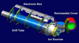
The sensor consists of four parts: the ion sources, the drift tube, the electronics and a closable cover (RTOF instrument, Figure 2).
Two ion sources are used to produce and extract the ions into the drift path. One ion source is optimized for neutral particles, which are ionized via electron impact (gas mode), the other source is optimized for the direct measurement of cometary ions (ion mode). For redundancy reasons both sources can be operated in ion and gas mode.
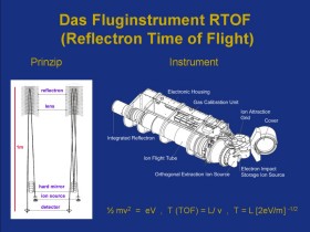
 The drift tube is the time-of-flight path for the particles. The ions originating from the ion sources are extracted with a short pulse (start pulse, duration: 2 µs) and accelerated using a constant voltage (U) to a constant energy (qU). After this acceleration process the particles drift through the tube - heavier ions drift slower than lighter ions. The ions reach the microchannel plate detector (MCP) where they generate another pulse (stop pulse). The time difference between start and stop pulse is used to directly calculate the mass of the ion. To increase the mass resolution the length of the drift path (and therefore the time of flight) is increased by reflecting the ion packets in the reflectron and the hard mirror (time-of-flight path, Figure 3 (left)).
 The electronic box is the housing for several electronic boards. These boards are controlling the voltages in the ion source, the acceleration voltage, the hard mirror, the reflectron, the pulsers and the supply voltages for the MCPs. Additionally, they report housekeeping values, move the cover motor and measure the exact time-of-flight of the ion packets. In order to reach a high mass resolution the measurement of the time difference between the start and the stop pulse has to be very accurate. The electronics developed in Lindau is able to resolve ion packets arriving within 0.55 nanoseconds. (see spectrum)
The entrance cover is necessary to protect the ion sources and sensitive microchannel plate detectors (MCPs) during launch and spacecraft maneuvers from fuel gases.
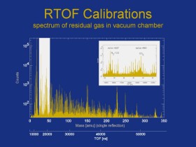
A spectrum of the residual gas in the vacuum chamber is measured in the Bern laboratory (Figure 4).
| Dr. Axel Korth | Active Co-Investigators and Scientists |
| Dr. Urs Mall | |
| Klaus Heerlein | Actual technical support |
| Alexander Loose |
|
ROSINA at Universität Bern |
|
|
Rosetta at ESA (Space Science) |
|
|
Rosetta at ESA (Missions) |
| © 2006, Max-Planck-Institut für Sonnensystemforschung, Lindau |
Axel Korth 09-10-2006 |