|
SOUSY - Svalbard - Radar
|
 |

|
SOUSY - Svalbard - Radar
|
 |
| Description | |
| Some examples of the SSR operation in 1999 |

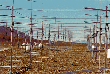
The photo shows part of the antenna array, consisting of 356 Yagi elements.
Operating frequency: 53.5 MHz, peak power: 60 kW
Mesosphere-stratosphere-troposphere (MST) radars have proved to contribute significantly to the studies of these processes. For this purpose the Max-Planck-Institut für Aeronomie has constructed and operates an MST VHF radar in Longyearbyen on Svalbard. Such MST radar studies are carried out in combination with other related observations, i.e. with the EISCAT Svalbard Radar for mesospheric and lower thermospheric studies, and with in-situ sounding by rockets (SvalRak) and other ground-based experiments, such as the imaging riometer (DMI) and OH spectrometer (UNIS) performed by several research groups in Longyearbyen. Studies of the Arctic stratosphere and troposphere are in conjunction with observations in Nyålesund and by aircraft performed by AWI.
The SOUSY Svalbard Radar (SSR) of the Max-Planck-Institut für Aeronomie (MPAe), which uses the main basic components of the mobile SOUSY radar, was set up in Longyearbyen in summer 1998. Long experiment operation took place in a few campaigns in 1999. The radar consists of a transmitter operating on 53.5 MHz at peak power of 60 kW (2.4 kW average), a high-gain Yagi-antenna array of 92 meters diameter, allowing five beam pointing directions at and close to the zenith, as well as radar control, receiver and digital signal processing units. This equipment is housed in two containers. The antenna is being modified by separating modules for reception in the radar interferometer and imaging mode.
Some main scientific objectives of this new project SSR, performed by the MPAe, are: Studies of tides, gravity waves and turbulence in the mesosphere and their interaction, the structure and dynamics of Polar Mesosphere Summer Echoes, and studies of Arctic stratosphere-troposphere dynamics related to the formation of Polar Stratospheric Clouds and to stratosphere-troposphere exchange processes.
SOUSY stands for SOUnding SYstem, which indicates that the SOUSY Svalbard Radar is used in a system of instruments to sound the atmosphere.
==========================================================================
Location	Geographic	Date		Main Objectives
		Coordinates
==========================================================================
Arecibo,	18 N, 67 W	April 1980 -	Multifrequency expt.,
Puerto Rico			Dec.  1981	Subtropical Meteorology
--------------------------------------------------------------------------
Rosenheim,	48 N, 12 E	March 1982 -	International ALPEX
Germany				April 1982	campaign
--------------------------------------------------------------------------
Andenes,	69 N, 16 E	Nov.  1983 -	International
Norway				June  1984	MAP/WINE campaign
--------------------------------------------------------------------------
Cape Canaveral,	29 N, 81 W	Feb.  1985 -	Wind measurements for
USA				May   1985	rocket/shuttle launches
--------------------------------------------------------------------------
McPherson,	38 N, 98 W	April 1985 -	Oklahoma-Kansas
USA				May   1985	PRE-STORM Program
--------------------------------------------------------------------------
White Sands,	32 N, 106 W	July  1985 - 	Antenna radiation pattern
USA				Oct.  1985	Cn^2, Wind
--------------------------------------------------------------------------
Lindau,		52 N, 10 E	Aug.  1986	Dual radar experiment
Germany						Reynold stress
--------------------------------------------------------------------------
Andenes,	69 N, 16 E	June  1987 -	International MAC/SINE
Norway				March 1990	and MAP/EPSILON campaigns
--------------------------------------------------------------------------
Andenes,        69 N, 16 E      June  1994 -    ALOMAR SOUSY
Norway                          March 1998
--------------------------------------------------------------------------
Svalbard,       78 N, 16 E      June  1999 -    SOUSY Svalbard Radar (SSR)
Norway                          present
==========================================================================
Transmitter:
-----------
Frequency ........................... 53.5 MHz
Pulse Peak Power .................... 60   kW
Duty Cycle .......................... 4%
min. Pulse Length ................... 1 microseconds

Antenna:
-------
Single Element ...................... 4-element Yagi
Number of Elements .................. 356
Beamwidth ........................... 4.5 degrees
Gain ................................ 33  dBi
Pointingdirections :
                    vertical, 5 ° to NE, SE, SW, NW
Separable  into modules
| © 2006, Max-Planck-Institut für Sonnensystemforschung, Lindau |
Rüster 21-01-2000 |