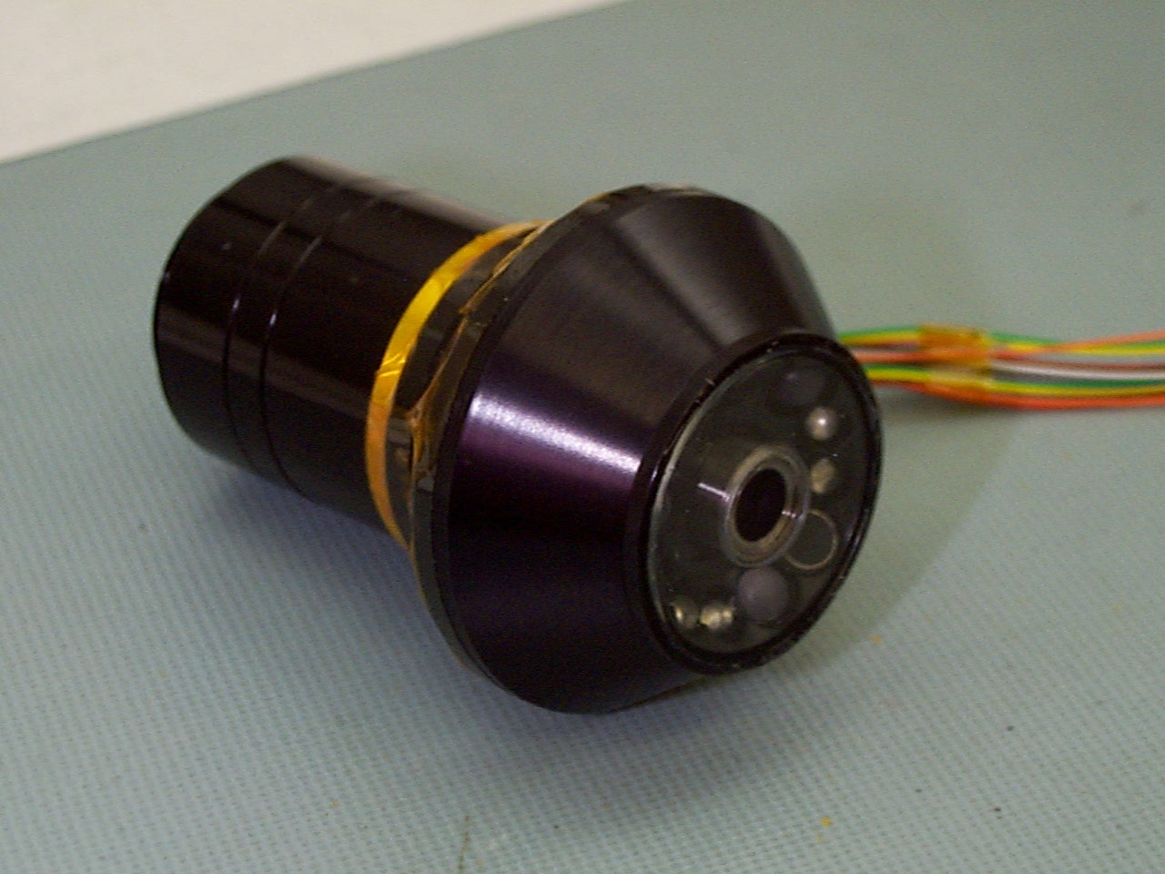
 This
picture shows the lamp assembly and the optical head. The wires form the
electrical interface to the Paw system.
This
picture shows the lamp assembly and the optical head. The wires form the
electrical interface to the Paw system.
Firstly, one cannot use the natural ambient light on Mars to illuminate
a sample because the microscope itself will cast a shadow over it. Hence,
you need an illumination system. Secondly, the depth of field specifies
the distance over which an object will appear focussed. The focus of the
Beagle 2 microscope will be 12 mm from the front surface. The depth of
field, however, is only 40 microns. Any part of the target in front of
or behind the focus position by more than this amount will be out of focus.
Hence, to ensure you get a sharp image, you need a focussing mechanism
which translates the microscope towards or away from the sample.
The Beagle 2 instrument has several natural interfaces. The illumination
system and the optics are so compact that they naturally form one work
package. The detector element forms a second work package. These two elements
are joined by a tube which provides a mechanical interface and a light-tight
structure of significant strength. The translation stage forms a fourth
work package.
The illumination system comprises 12 LEDs arranged symmetrically around the aperture of the microscope. There are four colours - red, green, blue, and UV (375 nm). The UV LEDs have been selected to look for possible fluorescence of materials during imaging. This would be particularly interesting for an exobiology lander in view of the potential fluorescence of lichens etc.
The RGB LEDs run at 10mA each, the UV at 8 mA. The voltage supply is 6 V. The power is 60 milliwatts per LED (48 milliwatts for the UV). Total integrated power is therefore 684 mW when all lights are on. The electrical interface for the illumination system comprises 15 wires - 12 supply lines and 3 ground wires. These wires run under the microscope body to a connector box on the Paw. The connector is a nano-D connector.
The optics and illumination system are provided by the Lunar and Planetary
Laboratory of the University of Arizona
(contacts: Peter Smith, Roger Tanner, and Robert Reynolds).
This
picture shows the lamp assembly and the optical head. The wires form the
electrical interface to the Paw system.
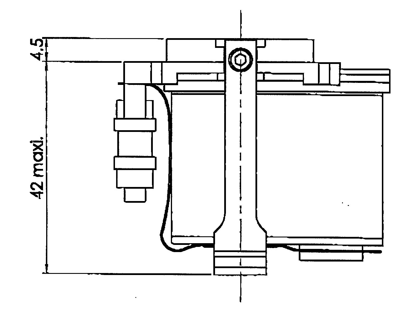 A technical
drawing of the structure of the detector head. The CCD is at the top and
light comes from the top onto the detector. The connector is to the left.
The whole piece is held together by the vertical bracket.
A technical
drawing of the structure of the detector head. The CCD is at the top and
light comes from the top onto the detector. The connector is to the left.
The whole piece is held together by the vertical bracket.
In designing the optics it needed to be noted that the CCD has a front
window. The window is 0.63mm for the thickness and the material is Sapphire.
The distance between the top of the window to the CCD plane is 1.12mm.
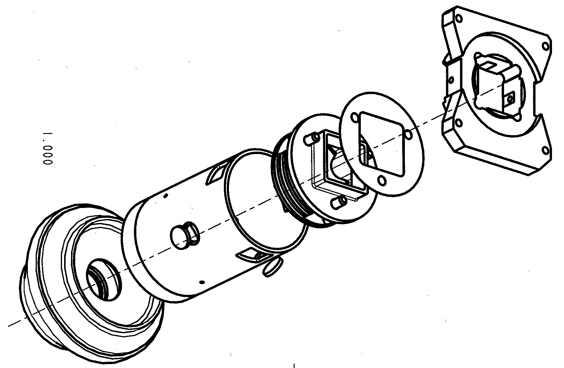 The tubular
structure holding the optical head (lower left) which interfaces with the
detector. The detector interface plate is shown on the top right.
The tubular
structure holding the optical head (lower left) which interfaces with the
detector. The detector interface plate is shown on the top right.
A Thumb for the Paw is required to bring the microscope head to a distance equivalent to the working distance from the target thereby reducing the travel required for the stepper motor.
The translation stage is attached to the Paw and is the responsibility
of the University of Leicester (contact Shaun Whitehead).
| Element | Mass [g] | Margin [g] |
| Optics | 25 | 10 |
| Illumination system | 25 | 10 |
| Structure | 20 | 10 |
| Detector module | 95 | 10 |
| Translation stage | 80 | 10 |
| Totals | 245 | 50 |
| Element | Peak Power [W] | Average Power [W] | Margin [W] |
| Illumination system | 0.684 | 0.684 | 0.1 |
| DC motor | 0.18 | 0.18 | 0.04 |
| Detector module | 3.5 | 2.0 | 0.3 |
| Totals | 4.36 | 2.86 | 0.44 |

![]()