CONSERT - Antenna


on Rosetta - S/C


Test Report


Properties


RO-OCN-TR-3002

Issue: 1

Revision: -

16.07.1999


Prepared by:

W.Boogaerts


Approval Sheet


prepared by: W.Boogaerts (signature/date)


approved by: Technical Department W.Engelhardt / J.Wedekind (signature/date)


approved by: Consert antenna Management Dr. Nielsen (signature/date)


____________________________________________________________________________ _

approved by: QA/PA W.Boogaerts (signature/ date)


Document Change Record


Iss./Rev.

Date

Pages affected

Description

1/-

16-07-1999

all


Distribution Record


Holder

Issue/Revision


Draft

1/-

1a

2


Consert-Documentation

MPAE

C


WB

W.Boogaerts

A/C


LB

L.Bemman

C


EN

Dr. Nielsen

A/C


Prof. Hagfors


HP

H.Perplies

A/C


KG

K.Gräbig


WE

W.Engelhardt

A/C


ESA

G. Gianfiglio

C


J-P. Goutail

A/C


Legend:

A - Approval
C - Copy
U - Updated Pages


Table of contents


1 General aspects *

1.1 Scope *

1.2 Antenna Folded on Attachment Plate *

1.3 Introduction *

1.4 Applicable Documents *

1.5 Reference Documents *

1.6 Test Equipment *

1.7 Acronyms *

2 Equipment under Test *

3 Test Conditions *

4 Test Requirements *

4.1 Visual Inspection *

Identification Labels *

4.1.2 General Appearance *

4.1.3 Thermal Finish *

4.1.4 Connectors *

4.1.5 Connector Savers *

4.1.6 Protective Covers *

4.1.7 Test Covers *

4.1.8 Harness *

4.1.9 Cleanliness *

4.1.10 Safety Devices *

4.1.11 Handling Provisions *

4.2 I/F Measurements *

4.2.1 Envelope Dimensions *

4.2.2 Support 1 *

4.2.3 Support 2 *

4.2.4 Support 3 *

4.2.5 Support 4 *

4.3 Physical Properties *

4.3.1 Mass Properties *

4.3.2 CoG / MoI *

4.3.3 Natural Frequencies *

4.4 Electrical Verifications *

4.4.1 Deployment Indicators *

4.4.2 Grounding *

4.4.3 Connector Locations ( JA4 / JA1 / JA2 / JA3 *

4.5 Safety Harness : Strings and Red Tag Items *

5 Non-Conformance (NCR) *

6 Procedure Sign Off Sheet *

7 Signatures *

8 Attachments *


List of Figures

Fig. 1 Antenna folded on Attachment plate *

Fig. 2 Antenna Overview *

Fig. 3 Grounding Schematic *

Fig. 4 Connector Location on Support - 1 *

Fig. 5 Connectors JA2 / JA3 on Pyro with Safety Caps on Support 3 *

Fig. 6 Safety Strings and Red Tag Items *


List of Tables

Table 1 Applicable Documents *

Table 2 Reference Documents *

Table 3 Test Equipment *

Table 4 Deployment Indicators *

Table 5 Grounding Values *

Table 6: Open Items *

Table 7 Signatures *

Table 8 Attachments *


  1. General aspects
    1. Scope
    2. This Testprocedure covers Project :

      Consert-Antenna (STM) on Rosetta - S/C


    3. Antenna Folded on Attachment Plate
    4. Fig. 1 Antenna folded on Attachment plate


      1.3 Introduction

      The purpose of this test is to determine the properties of the Consert-Antenna i.e. dimensions , reference point , interface pattern measurements , surface flatness of attachment plate, mass , centre of gravity , natural frequencies , electrical verification , etc..


    5. Applicable Documents
    6. Table 1 Applicable Documents

      no.

      document name

      document number

      Iss./Rev.

      AD1

      Consert Orbiter Antenna MICD

      RO-OCN-DW-3001

      2/E

      AD2

      General Background on Handling of the Orbiter Antenna and on Terminology Consult

      RO-OCN-DW-3019

      Version 1.3

      AD3


    7. Reference Documents
    8. Table 2 Reference Documents


      no.

      document name

      document number

      Iss./Rev.

      RD1

      EIDA

      RO-EST-RS-3001

      2/0

      RD2

      EIDB

      RO-EST-RS-3001

      1/0

      RD3

      EIDC

      RO-EST-RS-3001

      1/1

      RD4

      Space Engineering

      ECSS-E-10-03 / 5.1.16

      Draft 01F

      RD5

      Payload units STM build standard description

      TOS-MMS/1998/550/ln/JCS

      0

      RD6

      STM-test objective and built-standard definition

      RO-DSS-TN-1027

      2


    9. Test Equipment
    10. Table 3 Test Equipment


      Nr.

      Instr. / Equipment Description

      Manufacturer

      Model/Type-Nr.

      Inv. Nr.

      Calibration

      Last Next

      1

      Digital Caliper Rule

      Minimax

      K/03 20118

      94096


      2

      Knife Edge Straight-Edge

      Hauser


      3

      Thickness Gauge

      Orion/Germany


      DIN 2275

      4

      Balance

      Sartorius


      86070100


      5

      Centre Microscope

      Hensold

      65576


      6

      X/Y/Z-Digital Table

      Heidenhain

      PT855


      7

      Multimeter

      Keithly


      90011200


      8

      Low-Resistance Measurement

      Keithly

      195


    11. Acronyms

    MPAe Max-Planck-Institut für Aeronomie

    STM Structural and Thermal Model

    AD Applicable Document

    RD Reference Document

    FM Flight Model

    Hz Hertz

    Q-Level Qualification Level

    M Mass

    mm millimeter

    g Acceleration

    wrt. with respect to

    I/F Interface

    URF Unit Reference Frame


  2. Equipment under Test
  3. The Structural and Thermal Model (STM) of the Consert Antenna is mass and thermal representative of the Consert Antenna (FM). The size of the Antenna is 1135 mm x 100 mm x 125 mm. The Antenna weight is 1.45 kg.


  4. Test Conditions
  5.  

    Cleanliness: 100 000

    Temperature: 20 ° C

    Humidity: < 50 %


    Fig. 2 Antenna Overview


  6. Test Requirements
    1. Visual Inspection
    2.  

      1. Identification Labels

    3. General Appearance
    4. OK

       
    5. Thermal Finish
    6. Plasmocer Black and White

      Iridite ; PUI Black Paint


    7. Connectors
    8. OK

       
    9. Connector Savers< /FONT>
    10. N/A for STM

       
    11. Protective Covers
    12. None

       
    13. Test Covers< /TD>
    14. None

       
    15. Harness
    16. See Material List

       
    17. Cleanliness
    18. Visible Clean

       
    19. Safety Devices
      • Safety Caps on Connectors JA2 / JA3

      for Pyro-Connection

      • Safety Strings and Red Tags on

      Supports 2 and 4


          1. Handling Provisions

      To be handled by hand with gloves in class 100000 clean room


        1. I/F Measurements
        2. Step

          Specification

          Actual

          Remarks

          1. Envelope Dimensions
          2. (Folded Antenna)


          L

          W

          H

          1135 mm

          100 mm

          125 mm

             
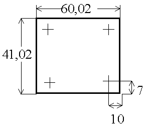
        3. Support 1
        4. (Holes-Nr. Clockwise from upside)

          1. Mounting Hole
          2. Position URF

            Tol.: ± 0,1 mm


          1

          2

          3

          4(R)

          Xu Yu

          0 36

          36 36

          36 0

          0 0


          Xu Yu

          -0,14 36,13

          35,98 36,01

          36,12 0,16

          0 0


        5. Hole Diameter
        6.  

          1

          2

          3

          4

          4,3 -0/+0,1 mm

          4,3 -0/+0,1 mm

          4,3 -0/+0,1 mm

          4,3 -0/+0,1 mm

          4,24

          4,24

          4,23

          4,23

           
        7. Spot Face Diameter
        8.  

          1

          2

          3

          4

          N/A

             
        9. Mounting Feet
        10. Dimensions

          1

          2

          3

          4


        11. Mounting Feet Thickness
        12. 1

          2

          3

          4

          4 0/0,1 mm

          4 0/0,1 mm

          4 0/0,1 mm

          4 0/0,1 mm

          4,06

          4,04

          4,06

          4,05

           
        13. Mounting Feet Contact
        14. Area

          1

          2

          3

          4


        15. Isolation Bushes
        16. None

             
        17. Surface Flatness
        18. 100 m


          Step

          Specification

          Actual

          Remarks

        19. Support 2
        20. (Holes-Nr. Clockwise from upside)

          1. Mounting Hole
          2. Position URF


            Tol.: ± 0,1 mm


          1

          2

          3

          4(r)

          Xu Yu

          0 41

          20 41

          20 0

          233 -33

          Xu Yu

          -0,10 40,99

          19,93 40,95

          19,99 -0,05

          0 0


          1 – 3 refer to 4(r)

          4(r) refer to 4(R) at support 1

        21. Hole Diameter
        22.  

          1

          2

          3

          4

          4,3 -0/+0,1 mm

          4,3 -0/+0,1 mm

          4,3 -0/+0,1 mm

          4,3 -0/+0,1 mm

          4,23

          4,22

          4,23

          4,22

           
        23. Spot Face Diameter
        24.  

          1

          2

          3

          4

          N/A

             
        25. Mounting Feet
        26. Dimensions

          1

          2

          3

          4


        27. Mounting Feet Thickness
        28. 1

          2

          3

          4

          4 0/0,1 mm

          4 0/0,1 mm

          4 0/0,1 mm

          4 0/0,1 mm

          4,04

          4,03

          4,06

          4,04

           
        29. Mounting Feet Contact
        30. Area

          1

          2

          3

          4


        31. Isolation Bushes
        32. None

             
        33. Surface Flatness
        34. 100 m


          Step

          Specification

          Actual

          Remarks

        35. Support 3
        36. (Holes-Nr. Clockwise from upside)

          1. Mounting Hole
          2. Position URF


            Tol.: ± 0,1 mm


          1

          2

          3

          4(r)

          Xu Yu

          0 41

          40 41

          40 0

          578 -33

          Xu Yu

          -0,01 41,03

          39,98 41,12

          40,01 0,07

          0 0

          1 – 3 refer to 4(r)

          4(r) refer to 4(R) at support 1

        37. Hole Diameter
        38.  

          1

          2

          3

          4

          4,3 -0/+0,1 mm

          4,3 -0/+0,1 mm

          4,3 -0/+0,1 mm

          4,3 -0/+0,1 mm

          4,22

          4,23

          4,23

          4,22

           
        39. Spot Face Diameter
        40.  

          1

          2

          3

          4

          N/A

             
        41. Mounting Feet
        42. Dimensions

          1

          2

          3

          4


        43. Mounting Feet Thickness
        44. 1

          2

          3

          4

          4 0/0,1 mm

          4 0/0,1 mm

          4 0/0,1 mm

          4 0/0,1 mm

          4,05

          4,07

          4,04

          4,07

           
        45. Mounting Feet Contact
        46. Area

          1

          2

          3

          4


        47. Isolation Bushes
        48. None

             
        49. Surface Flatness
        50. 100 m


          Step

          Specification

          Actual

          Remarks

        51. Support 4
        52. (Holes-Nr. Clockwise from upside)

          1. Mounting Hole
          2. Position URF


            Tol.: ± 0,1 mm


          1

          2

          3

          4(r)

          Xu Yu

          0 41

          20 41

          20 0

          908 -33

          Xu Yu

          0,06 40,97

          19,90 40,98

          20,01 0,05

          0 0

          1 – 3 refer to 4(r)

          4(r) refer to 4(R) at support 1

        53. Hole Diameter
        54.  

          1

          2

          3

          4

          4,3 -0/+0,1 mm

          4,3 -0/+0,1 mm

          4,3 -0/+0,1 mm

          4,3 -0/+0,1 mm

          4,25

          4,24

          4,24

          4,24

           
        55. Spot Face Diameter
        56.  

          1

          2

          3

          4

          N/A

             
        57. Mounting Feet
        58. Dimensions

          1

          2

          3

          4


        59. Mounting Feet Thickness
        60. 1

          2

          3

          4

          4 0/0,1 mm

          4 0/0,1 mm

          4 0/0,1 mm

          4 0/0,1 mm

          4,05

          4,06

          4,08

          4,05

           
        61. Mounting Feet Contact
        62. Area

          1

          2

          3

          4


        63. Isolation Bushes
        64. None

             
        65. Surface Flatness
        66. 100 m


        67. Physical Properties
        68.  

          1. Mass Properties
          2. See RO-OCN-DW-3001

            STM Mass Breakdown (grams) (actuel)

            FM Mass predicted

            Remarks


            1447

            1450 ± 10

            With Cabling


          3. CoG / MoI
          4.  

            STM Measured

            FM Predicted

            Diff. In %

            Total Mass M


            CoG X

            Y

            Z


            502 mm.

            -22 mm.

            63 mm.


            MoI Ixx

            (wrt. CoG) Iyy

            Izz


            1.6 x 10⁻³ Kgm2

            1.6 x 10⁻¹ Kgm2

            1.6 x 10⁻¹ Kgm2


          5. Natural Frequencies

          See Vibration report RO-OCN-TR-3021


          STM

          Predicted for FM

          1st Natural Frequency X-Axis

          320


          1st Natural Frequency Y-Axis

          145


          1st Natural Frequency Z-Axis

          150


        69. Electrical Verifications
          1. Deployment Indicators
          2. Each Carpenter-Spring is supplied with an Resistor(R) to provide a deployment-check.

            See connector Location 4.4.3


            Table 4 Deployment Indicators


            Folded Antenna

            Deployed Antenna

            (to be measured after Deployment-Test)


            Connector

            JA4

            Specification


            Actual Value

            Specification

            Actual Value

            Carpenter Spring 1

            P 7 P 2

            R < 50 W

            0.4

            R > 1 MW

            > 1 MW

            Carpenter Spring 2

            P9 P4

            R < 50 W

            0.4

            R > 1 MW

            > 1 MW


          3. Grounding
          4. Fig. 3 Grounding Schematic

            Table 5 Grounding Values

            Description

            Specification

            Actual

            Dipoles / Mast-2

            £ 25 mW


            Mast-2 / Manchet-2

            £ 25 mW


            Mast-2 / Mast-1

            £ 25 mW


            Mast-1 / Manchet-1

            £ 25 mW


            Mast-1 / Support-1

            £ 25 mW


            Support-1 / Spacecraft

            £ 10 mW


            Support-2 / Spacecraft

            £ 10 mW


            Support-3 / Spacecraft

            £ 10 mW


            Support-4 / Spacecraft

            £ 10 mW


            Ground Stud /Spacecraft

            £ 2.5 mW


            Surfaces / ...

            < 1 kW

            > 1 kW

          5. Connector Locations ( JA4 / JA1 / JA2 / JA3


          Fig. 4 Connector Location on Support - 1

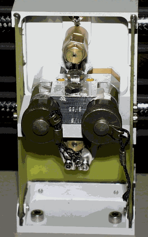
          JA4


          JA1


          Fig. 5 Connectors JA2 / JA3 on Pyro with Safety Caps on Support 3


        70. Safety Harness : Strings and Red Tag Items


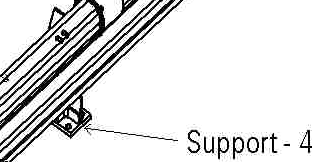
      Fig. 6 Safety Strings and Red Tag Items


      1. Non-Conformance (NCR)
      2.  

        Where any out of limits results is obtained during the test , the result shall be annotated clearly as being a test failure and the Non-Conformance-Reporting according to EID A

        Issue 1 , Rev. 0 Sec.: 3.3.8 and Section 8.33.1 will be initiated.

        A NCR Consert-Formsheet RO-OCN-MPAE-FO-007.doc is attached.

        A summery of all out of limits results (NCR-Overview) should be appended to the test report.

        A NCR-Overview Consert-Formsheet RO-OCN-MPAE-FO-007_ov.doc is attached.


      3. Procedure Sign Off Sheet
      4.  

        The identified test item has been successfully tested in accordance with the foregoing procedure and all open items (e.g. NCR's) are closed except those listed below:


        Table 6: Open Items


      5. Signatures
      6. Table 7 Signatures


      7. Attachments

      Table 8 Attachments

      No.

      Doc.Nr.

      Title

      Version

      Date

      Remarks

      1

      RO-OCN-DW-3001

      MICD

      2/D


      Item # 6