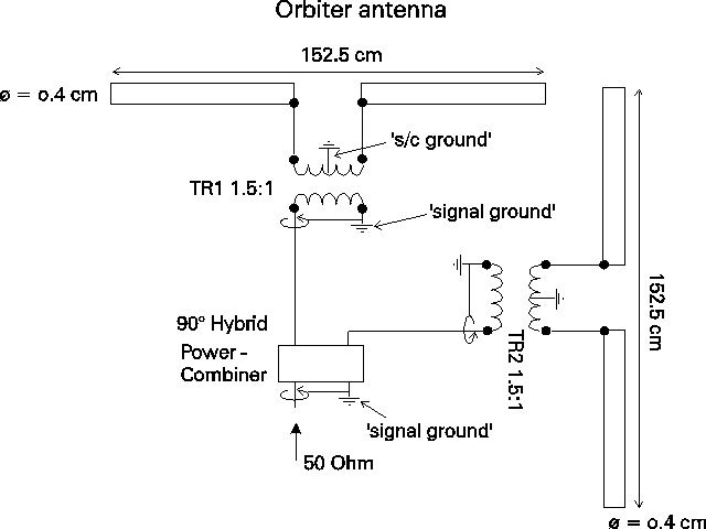

The impedance matching network is illustated in the Figure. The geometry of the antenna is such, that the two dipoles to a good approximation sees the same environment, and therefore will have nearly identical impedances.
Each diplole is cut to a length where the reaktive impedance is zero. For this length of the antenna elements the real impedance will be close to 75 Ohm. A transformer with ratio 1.5:1 transform this impedance to 50 Ohm, and at the same time it transforms the impedance,from balanced (dipole) to unbalanced (co-axial cable).
The 90 degrees phase differece between the dipoles is produced by a wide band transformer, part of the power combiner.(This transformer effectively mirrors the impedance in the center of a Smith diagram, and so produces an impedance that is complementary to the impedance of the other dipole). The signals of the two diploles are combined in this power-combiner.
- 's/c-ground' is the ground potential of the spacecraft and the antenna structure. The antenna structure has a low Ohmic electrically resistance, i.e.t here must be a low Ohmic resistance from the antenna structure over the supports to the spacecraft.
On the secondary side of the transformer the antenna signal is picked up by a coaxial cable with its center conductor and its shield placed across the secondary coil. The shield is on 'signal ground'. The coaxial cables coming from the two transformers are input to a power combiner. The output of the power combiner is picked by a coaxial cable. The shield of this coaxial cable is also on 'signal-ground'.
- 'signal-ground' is the ground potential of the coaxial shield carrying the antenna signal; the shield is on the same potential from the power combiner to the input on e-box.
Thus, 'signal ground' is separated from 'spacecraft ground'. The coaxial connector JA1 on the antenna foot must therefore have its ground isolated from the antenna foot.
The 4 supports placed on the spacecraft are for thermal (temperature) control purposes constructed of thermally isolating material. All material parts on the supports (including the antenna structure) are therefore short-circuited to 's/c-ground' by a thin metal strip (or this wire) placed on top of the thermally isolating material. The metal strip is so thin that it has a very low thermal conductivity so as not to upset the thermal balance.