CONSERT - Antenna
on Rosetta S/C
Thermal Vacuum Test Report
of the
Consert Orbiter Antenna STM
RO-OCN-TR-3006
Issue: 1
Revision: -
29.07.1999
Prepared by:
W.Boogaerts / H.Perplies
Approval Sheet
prepared by: W.Boogaerts / H.Perplies (signature/date)
approved by technical department: H. Perplies (signature/date)
approved by Consert-Management: Dr. Nielsen (signature/date)
approved by QA/PA : W.Boogaerts (signature/date)
Document Change Record
|
Iss./Rev. |
Date |
Pages affected |
Description |
|
1 / - |
29.07.1999 |
all |
|
Distribution Record
|
Holder |
Issue/Revision |
||||||||||||||||
|
Draft |
1/- |
1a |
2 |
||||||||||||||
|
Consert-Documentation MPAE |
C |
||||||||||||||||
|
WB |
W.Boogaerts |
A/C |
|||||||||||||||
|
LB |
L.Bemman |
C |
|||||||||||||||
|
EN |
Dr. Nielsen |
A/C |
|||||||||||||||
|
Prof. Hagfors |
C |
||||||||||||||||
|
HP |
H.Perplies |
A/C |
|||||||||||||||
|
KG |
K.Gräbig |
A/C |
|||||||||||||||
|
WE |
W.Engelhardt |
A/C |
|||||||||||||||
|
AF |
A.Fischer |
A/C |
|||||||||||||||
|
ESA |
G.Gianfiglio |
C |
|||||||||||||||
|
J-P. Goutail |
A/C |
||||||||||||||||
|
Legend: A - Approval |
|||||||||||||||||
Table of contents
1 General
*1.1 Introduction
*1.2 Applicable Documents
*1.3 Reference Documents
*1.4 Acronyms
*2 Test Arrangement
*3. Data acquisition
*3.1 Test Configuration in TV-Chamber
*4. Test Conditions
*4.1 Temperature cycle
*5. Test Steps
*6 Results
*6.1 Data printout
*6.2 Pictures after Test
*7 Procedure Sign Off Sheet
*8 Attachments
*
List of Tables
Table 1: Applicable Documents *
Table 2: Reference Documents *
Table 3: Temperature Sensor Locations *
Table 4: Signatures *
Table 5: Attachments *
List of Figures
Fig. 1 principle arrangement *
Fig. 2 Test Configuration in TV-Chamber *
Fig. 3 Temperature sensor locations on folded Antenna *
Fig. 4 temperature cycle *
Fig. 5 8-Cycle temperature plot *
List of Pictures
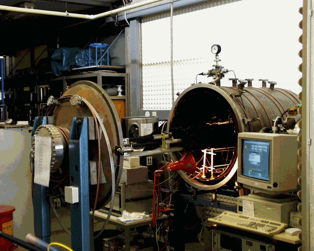
pict. 1 TV-Chamber with test equipment *
pict. 2 Thermal vacuum chamber with thermal box *
pict. 3 overview of the antenna sensors (immediately after test) *
pict. 4 sensor F5 *
pict. 5 sensor F8 *
pict. 6 sensor F7 *
pict. 7 support 2 *
pict. 8 support 4 *
This test report describes the thermal vacuum test of the STM CONSERT Orbiter-Antenna. The test has been performed according to the ‘Thermal Vacuum Test Procedure of the Consert-Antenna STM’ RO-OCN-PR-3006.
|
No. |
Document Name |
Document Number |
Iss./Rev. |
|
AD1 |
Consert Antenna Mechanical Interface |
RO-OCN-DW-3001 |
|
|
AD2 |
thermal vacuum chamber short description |
|
No. |
Document Name |
Document Number |
Iss./Rev. |
|
RD1 |
EIDA |
RO-EST-RS-3001 |
1/1 |
|
RD2 |
EIDB |
RO-EST-RS-3007 |
1/0 |
|
RD3 |
EIDC |
RO-EST-RS-3001 |
|
|
RD6 |
ECSS-10-03 |
Testing Procedures |
Draft |
MPAe Max-Planck-Institut für Aeronomie
STM Structural and Thermal Model
TV Chamber Thermal Vacuum Chamber
AD Applicable Documents
RD Reference Documents
TB Thermal Box
LN Liquid Nitrogen
DUT Device under Test
PID Proportional – Integral – Differential
LN Liquid nitrogen container
The cooling and heating of the DUT inside the TV-Chamber is performed by a PID Temperature control unit. The data are gathered by LabView Ò from National Instruments.
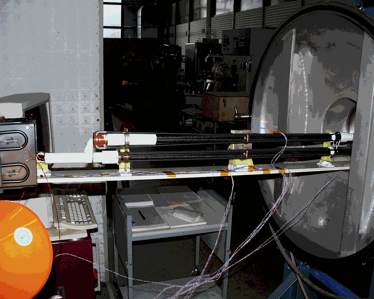
pict. 1. TV-Chamber with test equipment

Fig. 2 TV-Chamber with thermal box
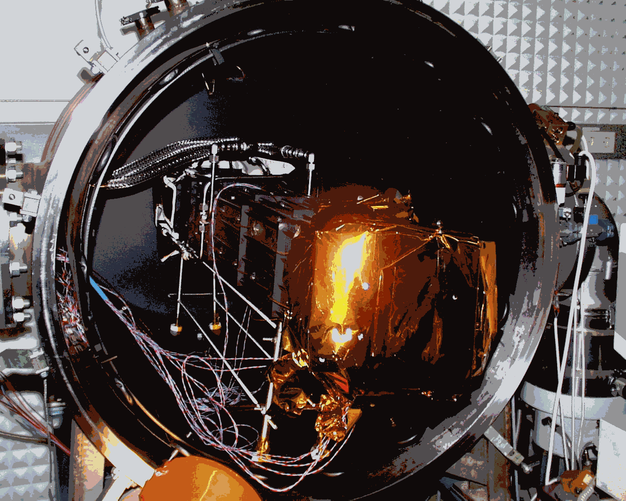
shroud liquid nitrogen pipes thermal box
pict. 2 Thermal vacuum chamber with thermal box
Data Acquisition and recording by PC / Network (8 channels )
Software: Lab Viewâ
Fig. 3 Overview Acquisition System
3.1 Test Configuration in TV-Chamber
Fig. 2 Test Configuration in TV-Chamber
3.1 Temperature Sensors
Table 3: Temperature Sensor Locations
|
Channel No. |
Temperature sensor location |
|
1 2 3 4 5 6 7 8 |
F1 : at the top of the shroud F2 : at the bottom of the shroud F3 : at the top of the thermal box F4 : at the bottom of the thermal box F5 : at the manchet 1 F6 : at the aluminium base plate at support-3 F7 : at the pyro cutter on support-3 F8 : at the carbon fibre part of mast 2 |
Fig. 3 Temperature sensor locations on folded Antenna
Temperature at different points of the antenna:
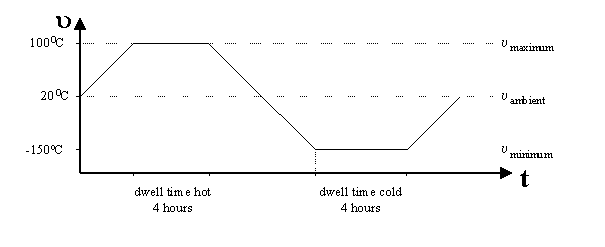
no-operating hot steady state: + 100° C
no-operating cold steady state: - 150 ° C
Pressure: <10-5mbar (1mPa)
Environment Temperature : about 20 ° C
Humidity : < 50 %
The STM CONSERT Orbiter antenna was tested from 19. July – 29. July 1999.
|
No. |
Test step |
Verified |
Pictures-Nr. |
Remarks |
|
Unpack and visual inspection |
||||
|
1. |
Unpack the Antenna immediately before installation in the TV chamber. Handle it only with cleanroom compatible gloves. |
4 |
||
|
Preparation of Test Facility |
||||
|
2. |
check TV chamber |
4 |
||
|
3. |
Integrate Mechanical Supports into TV-Chamber |
4 |
||
|
4. |
Integrate TB on Supports in Chamber |
4 |
||
|
Integration to test facility |
||||
|
5. |
attach Temperature sensors on the Antenna , in TV chamber, and on Thermal Box as described |
4 |
||
|
6. |
Integrate Antenna into TB |
4 |
||
|
7 |
Place MLI on the ends of TB |
4 |
||
|
8. |
connect the leads of the Temp. Sensors , TB- heaters and LN-Connections to the TV chamber feedthrough connector and connect the power supply outside the chamber |
4 |
see pict. 2 |
|
|
9. |
Pump down TV chamber pressure to <=10-5mbar |
4 |
||
|
Cycle |
Step |
Test step |
Verified |
Prints |
Remarks |
|
Test flow steady state, hot and cold environmental conditions |
|||||
|
1. |
Warm-up TB to 100 ° C by switching on Power Supplies |
4 |
|||
|
2. |
Dwell Time 4 Hrs. at 100 ° C |
4 |
|||
|
3. |
Cool down TV chamber shroud by connecting to LN-Container |
4 |
|||
|
4. |
Cool Down TB to -150 °
C |
4 |
|||
|
5. |
Dwell Time 4 Hrs. at -150 ° C |
4 |
|||
|
6. |
Close LN-Container to Shroud and TB |
4 |
|||
|
7. |
Start with Step 1 for next Cycle |
4 |
|||
|
End of Test after 8 Cycles |
|||||
|
Let System Heat-up to Ambient |
4 |
Print-Nr. |
|||
|
Switch off all supplies |
4 |
||||
|
Acquire temperature data at steady state (after approx. 1h) |
4 |
||||
|
Purge TV chamber with dry nitrogen or synthetic air |
4 |
||||
|
Open TV chamber |
4 |
||||
|
Step |
Test step |
Verified |
Pictures |
Remarks |
||
|
Disintegration of System |
||||||
|
Dismount all LN- ,Temp. Sensors and Heating-Connections from TB |
4 |
|||||
|
Remove MLI |
4 |
|||||
|
Dismount temperature sensors from Antenna |
4 |
|||||
|
Pull out Antenna out of TB |
4 |
|||||
|
Remove Temp. Sensors |
4 |
|||||
|
Pack Antenna into clean bag and into transport container |
4 |
|||||
|
End of the test |
||||||
Visual inspection of the antenna following the test:
– Sensor F6 lost good contact with the mounting plate during the third cycle.
Since the overall temperature variations of the antenna were similar for all cycles, we conclude (with reference to the last two points above) that temperatures at F5 and F6 were comparable to the temperatures during the first cycles.
6.1 Data printout
Fig. 5 8-Cycle temperature plot
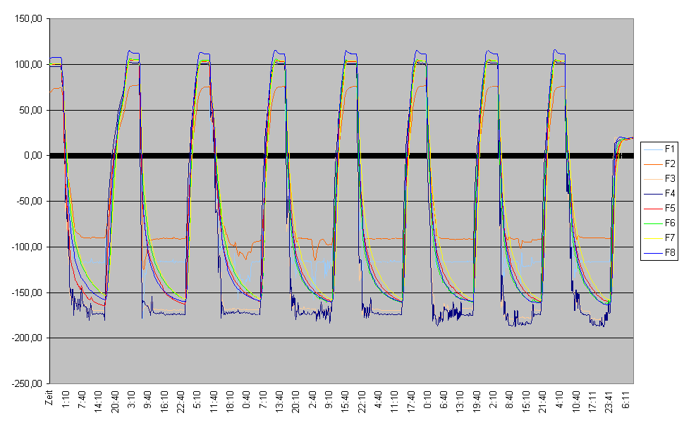
F1 – F4 Sensors of the cooling system
F5 – F8 Sensors of the antenna, see Fig. 3
pict. 3 overview of the antenna sensors (immediately after test)
sensor F5 ‘antenna 1’ sensor F6 ‘mounting plate’ sensor F8 ‘antenna 4’
sensor F7 ‘pyro-cutter’
pict. 4 sensor F5
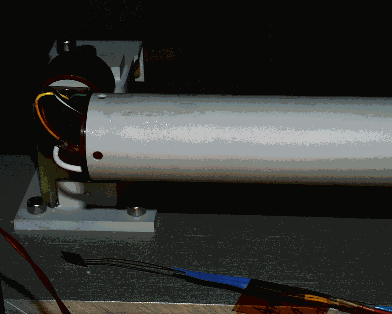
sensor F5 ‘antenna 1’ should be at manchet 1, has been lost after 1st cycle
sensor F8 ‘antenna 4’ at carbon fibre mast 1
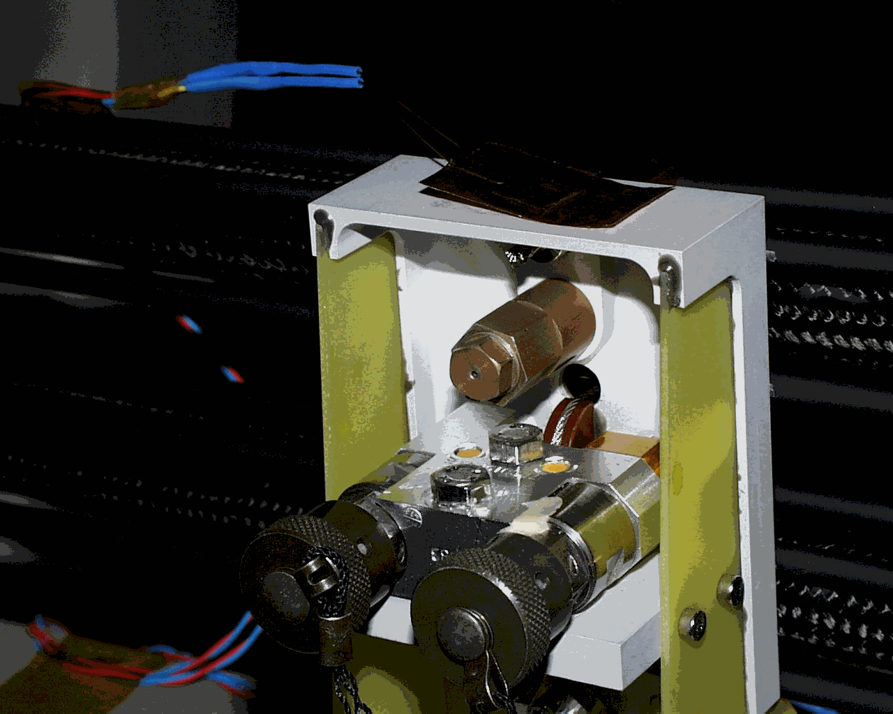
sensor F7 ‘pyro-cutter’ pyro
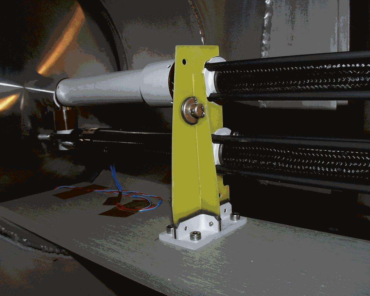
pict. 7 support 2
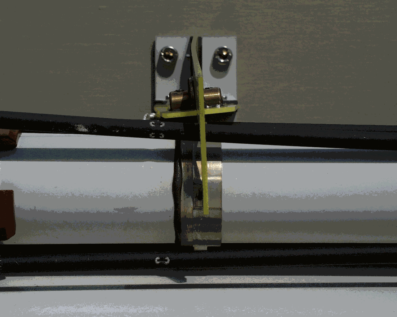
‘bended’ support 2
pict. 8 support 4
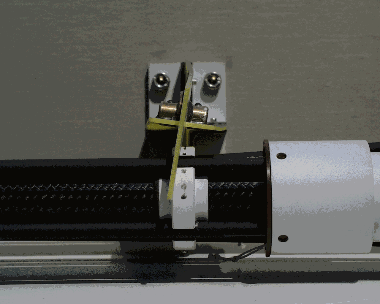
‘bended’ support 4
The identified test item has been successfully tested in accordance with the foregoing procedure.
|
No. |
Doc.Nr. |
Title |
Version |
Date |
Remarks |
|
1 |
-.- |
LabView print |
1 |
99.07.29 |
|