RAPID Ion Spectrometer IIMS
 Table of technical parameters below.
The Nuclei Detector SCENIC
The centerpiece of the IIMS sensor system is the so-called SCENIC detector
head. The acronym stands for "spectroscopic camera for electrons, neutral
and ion composition". In essence SCENIC is a miniature telescope composed
of a time-of-flight (TOF) and energy (E) detection system. The noval aspect
is the imaging of flux distributions and the capability to identify energetic
neutral atoms (ENA) in a certain energy band.
The particle identifying function of the SCENIC spectrometer is obtained
from a two-parameter measurement: The particle velocity (V) and the energy
(E) are measured as independent quantities, the particle mass A is then
uniquely determined either by computation (A E/V2) or by statistical analysis
in two-dimensional (V, E) space with the mass A as the sorting parameter.
Actually the velocity detector measures the flight-time (T) the particle
needs to travel a known distance in the detector geometry.
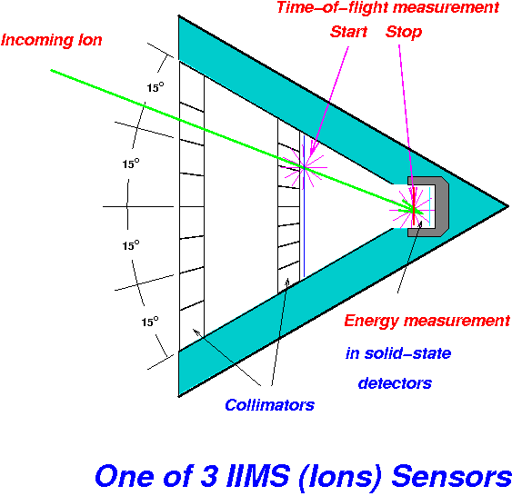
The figure shows a cross-section of the SCENIC detector. A particular
feature is the triangular structure with a 60° opening angle. The energy
measuring solid state detectors (SSD) are mounted in the apex at the rear
of the system. A group of two SSDs (an energy detector ED and a back detector
BD) is combined in an anticoincidence condition for high energy electron
detection. The flight-time (T) measuring system is the entry element of
the telescope. It is essentially composed of a thin foil (5 g/cm2
carbon foil with Al coating) and the front surface of detector ED. The
distance between the foil and detector ED along the line of symmetry is
the nominal flightpath s for the T-measurement.
Particles passing through the telescope release "secondary electrons"
(SE) from the entry foil. The SE are accelerated and directed to a microchannelplate
(MCP) for detection. The MCP output signal constitutes the START signal
for the T-measurement. Upon impact of the particle on detector ED secondary
electrons are ejected from its surface as well. These SE are transferred
to the STOP-MCP by a technique similar to the start electrons. The STOP
signal completes the T measurement.
The energy E of the incident particle, reduced by the loss in the START
foil, is measured in detector ED. For sufficient high energies the particle
is able to penetrate detector ED and to strike the back detector (BD).
This leads to the elimination of the event from analysis.
The START foil is shown as an elongated rectangle. The design of the
START-system is such that the SE transfer to the MCP is not only isochronous
but also position preserving: Four read-out anodes behind the START-MCP
(not shown) correspond to four contiguous segments on the entry foil and
each of these forms a 6° by 15° viewing cone with the ED detector
in the back of the system. In a sense this geometry can be considered a
degenerated case of a "projection camera" with only one pixel in the back
plane. In this special case the "virtual" image plane coincides with the
entrance foil.
Incident particles are strongly collimated before they reach the T/E-telescope.
Two microchannel collimators define a highly anisotropic field-of-view
(FOV) with 6° lateral and 60° polar opening. A set of plates between
the collimating elements with alternating potentials (0 and +Udef) forms
a linear electrostatic deflector (DEFL). The primary purpose of DEFL is
to protect the instrument from overloads due to large fluxes of low energy
particles (e.g. solar wind plasma). Some selected technical parameter of
the SCENIC head are listed in the table below.
The relative high gain of the active collimator (approx. 10) allows
efficient separation of energetic neutral atoms (ENA) from ions for energies
up to 100 keV. This energy band is generally considered important for magnetospheric
neutrals produced in the ring current region.
Technical parameters of the SCENIC head
| Flightpath s (mean) |
34 mm |
| Field-of-view (total) |
6° × 60° |
| Polar angles |
4 × 15° |
| E-Detector (ED) |
|
| Area/Thickness |
5 × 15 mm2/300 µ |
| B-Detector (BD) |
|
| Area/Thickness |
5 × 15 mm2/300 µ |
| START foil* |
-- |
| Al/Lexan/Al |
63 nm/ 83 nm /63 nm |
| Deflection voltage |
0 - 10 kV |
*The high-quality foils were
manufactured by the Luxel Corporation, Friday Harbor, WA (USA)
|