RAC
Robotic Arm Camera
|
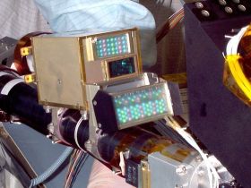
The Max Planck Institute for Solar System Research (MPS), Katlenburg-Lindau, has developed the Robotic Arm Camera (RAC) (figure) in collaboration with the University of Arizona. It also provided the focal plane with the Charge Coupled Device (CCD) detector for the Optical Microscope (MECA-OM). RAC and MECA-OM have the same CCD and share a common readout electronics that is located elsewhere and can serve one detector (RAC or MECA-OM) at a given time.
The RAC was originally built for the Mars Surveyor Lander 2001. After canceling of that mission the RAC was stored in a clean room and re-activated in 2005. Its development and integration was largely covered by funds from the Max Planck Society. Since 2007 the German Space Agency (DLR) supports the operation of the instrument during Phoenix surface operations. This support also includes participation in Operational Readiness Tests (ORT) prior to landing.
|

Figure: The Robotic Arm Camera (RAC). The box-shaped chassis of the camera measures 78 mm x 61 mm x 62 mm (LxWxH). The lighting assemblies (above and below the camera objective) include a total number of 26 red, 26 green and 52 blue Light Emitting Diodes (LED). Credit: LPL.
|
Science objectives
RAC images characterize soil material in terms of color, grain size (down to < 50 microns), texture and porosity. The RAC has the following science objectives:
- Support the selection of the digging site
- Characterize a soil patch prior to digging (together the Surface Stereo Imager, SSI)
- Characterize trench walls and search for sand/ice layering
- Characterize soil samples in the scoop prior to delivery to other instruments on the lander deck (MECA, TEGA)
- Characterize the surface below the lander
The Instrument
|
The RAC is a camera with a double Gauss lens system and a CCD (Charge Coupled Device) detector. The focus can be adjusted by moving the lens system back and forth with respect to the fixed CCD. In that way the object to be imaged can be placed at any distance (> 13 mm) from the front window of the camera. In extreme close-up mode the imaging scale is 1:1 and each pixel corresponds to 23 microns at the location of the target.
The RAC also has a transparent sapphire cover that protects the front window of the camera against dust contamination. During normal image acquisition the cover shall be open.
The RAC has two lighting units that are composed of red, green and blue Light Emitting Diodes (LEDs) and are mounted, respectively, above and below the camera chassis (figure). These LED assemblies allow lighting of targets in all three wavelength ranges. Acquiring images under these three lighting conditions provides color information of the targets and allows for generation of true-color images of these targets.
|

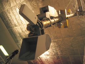
Figure: Robotic Arm (RA) with Robotic Arm Camera (RAC) and scoop. The 4-needle device that is located between scoop and RAC is the Thermal and Electrical Conductivity Probe (TECP). This probe is part of the MECA payload (although it is not included in the MECA box on the lander deck). Credit: JPL and MPS.
|
Characteristics of the RAC
| Magnification |
up to 1 |
| Distance to object |
11mm - infinite |
| CCD |
256 x 512 pixel |
| Resolution |
23 microns/px |
| Mass |
0.415 kg |
| Dimensions |
116 x 61 x 76 mm |
| Light source |
26 red, 26 green and 52 blue LEDs |

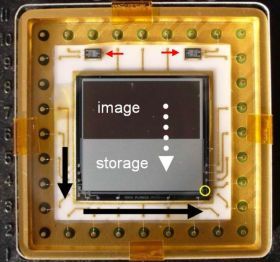
Figure: RAC and MECA-OM CCD Detector ("Max Planck Chip"). The dotted white arrow indicates the fast shift of data from image zone to storage zone. The pixel charges of the latter zone are then moved towards the readout unit (yellow circle), where they are recorded as analogue voltages. The red arrows indicate temperature sensors of type "AD590". The image is about 30 mm from left to right. Credit: MPS.
|

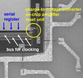
Figure: Zoom of previous figure: Readout unit of the RAC CCD Detector.
|
The Team
| Horst Uwe Keller (PI) |
| Wojtek Markiewicz |
| Stubbe F. Hviid |
| Rainer Kramm |
| Hermann Hartwig |
| Hermann Arnemann |
| Helmut Schüddekopf |
| Walter Goetz |
Related links
